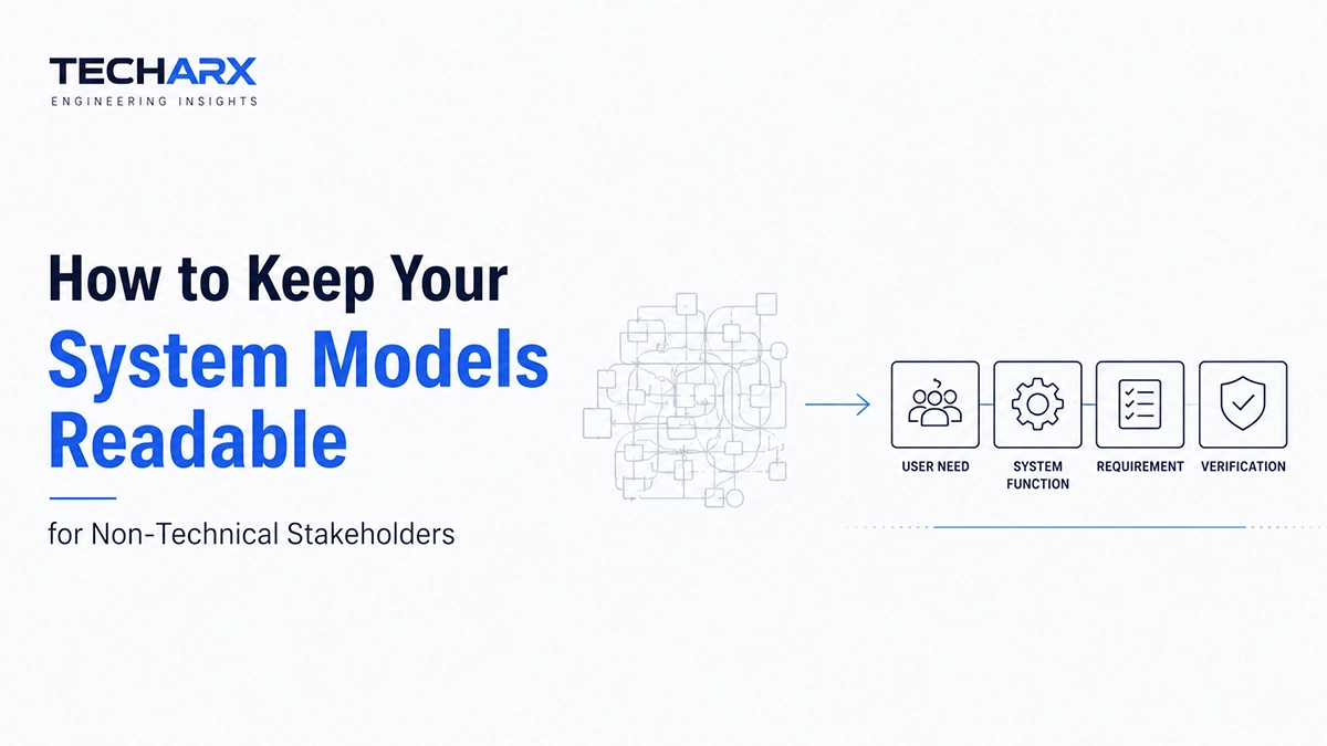
Most system models fail their audience not because the engineering is wrong, but because the diagram in front of a stakeholder was never meant for their eyes. A block definition diagram packed with ports, flows, and internal interfaces tells an engineer exactly what they need to know. It tells a program sponsor almost nothing except that the model looks complicated and they should probably just nod and approve it.
That gap is where systems engineering projects quietly go sideways. Stakeholders sign off on a review without actually understanding what they confirmed, and the disconnect surfaces months later as a change request, a missed requirement, or a redesign. Boehm’s defect-cost curve from Software Engineering Economics still holds up here: a misunderstanding caught during requirements analysis costs roughly 1x to fix, but the same gap discovered at integration or in the field can run 10x to 100x or more. Readable models aren’t a nice-to-have. They’re how you catch that gap while it’s still cheap.
Stop Showing Everyone the Same Diagram
Most MBSE efforts start with one inclusive model and show the same view to everyone. A SysML model can represent many projections of the same underlying information, and the ISO/IEC/IEEE 42010 idea of viewpoints and views is there for this specific purpose, different stakeholders get different lenses on the same model.
An executive sponsor requires a use case diagram that illustrates what the system performs for users. A test lead requires a requirements diagram that maps stakeholder requirements to verification criteria. A hardware engineer requires an internal block diagram with the complete port and flow detail. None of these individuals needs the view of others, and compelling everyone to refer to one master diagram guarantees that most of them mentally lose focus within the first five minutes.
Name Things the Way People Actually Talk
The naming conventions used are typically easy for the author of the model but difficult for everyone else to understand. For example, LRE\_CTRL\_CAL might sound logical for your engineering team, but for a program manager or other non-engineering reviewer you have already lost their attention before you have even had a chance to explain what the block does. Investing in sysml training helps teams build habits like this early, for instance, “Lighting Controller Calibration” could more or less replace that acronym and it would not make the model any less accurate or elegant. You would, however, eliminate that silent translation step that your reviewer had to go through on that last diagram and the one before that and the one before that.
Keep Diagrams Small and Give Them One Job
A diagram that attempts to visualize an entire system all at once is impossible to read, regardless of the quality of the SysML. A good model structure implies that each diagram is designed for a specific purpose and you intentionally limit the number of elements that it contains. If a reviewer requires more details, they can drill down through containment to navigate deeper instead of having to read a diagram as large as a wall.
This is more a problem of discipline than of tools. SysML provides you with the mechanism, decomposition, containment, diagram filtering, to hide ports, internal flows, or subordinate blocks depending on who’s looking. However, most teams do not consistently apply this, meaning that diagrams are allowed to grow organically until they document everything and communicate nothing.
Lead With Behavior, Not Structure
For people who are not familiar with technical details, it is best to introduce use case diagrams and requirements diagrams first. These correspond to what a stakeholder is already interested in: what the system’s functions are and whether they meet the requirement the stakeholder put forward. When it comes to technical design reviews, you can use internal block diagrams with ports, connectors, and signal flows as the audience already has the necessary technical knowledge.
One of the most important aspects a model can reveal to a stakeholder is requirements traceability: showing how their original requirement is linked to the design element. If the trace is too crowded and all intermediate traces are shown simultaneously, it will be just a mess of lines with no real value. Show the trace that is useful for the person looking at the model rather than the whole traceability graph.
Let Annotations Carry the “Why”
Diagrams might be nice, but they don’t talk about why something is there. For example, an interface on a block might be “Because XYZ function needs it, of course!” but that doesn’t explain why XYZ function needs it, or why the block provides it. A constraint on a capability might be there to relate that capability to something else. If you want to show that electric motor start-up capability must follow the calibration capability, you should put in a note that says why.
Putting it Into Practice
None of this depends on a better tool. It depends on habits: assigning viewpoints deliberately, naming things in plain language, scoping diagrams tightly, leading with behavior for lay audiences, and annotating the reasoning behind technical decisions. Building that discipline across a team usually means investing in real modeling fluency rather than hoping people pick it up ad hoc.
Readable models don’t happen by accident, and they don’t happen because the modeling tool has a “simplify” button. They happen because someone on the team treated the model as a communication tool first and an engineering artifact second, and built the habits to prove it at every review.