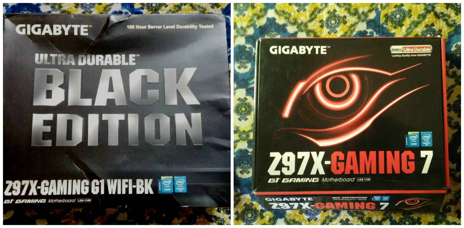
Introduction: Where do we begin?
Devil’s Canyon refresh has brought in some additional features over the first generation Haswell platform, and as expected, motherboard manufacturers have approached this update with their own ways. GIGABYTE has been experimenting with their entire product range for quite some time, and in their evolution of the Ultra Durable moniker, they have moved away from including only the VRM/Power Delivery aspects and expanded the featurette to cover more things. From Z87, Ultra Durable has started to cover aesthetics as well, with different VRM Heatsink color schemes for different SKUs (UD7 – Brown, UD5 – Gold, UD4 – Red, UD3 and lower – Blue). Interestingly, GIGABYTE had a specific color scheme to their gaming and overclocking oriented boards (Orange for OC, Green for Sniper etc.) but with Haswell refresh we saw that segregation spread across other boards as well. With Z97, however, we are seeing GIGABYTE adopt the ‘Gaming’ keyword into their motherboard names. What’s interesting here is that the earlier consumer range remains, and the entire Gaming/Sniper range is given a Red/Black makeover. I suspect this is to match the huge ongoing demand for gaming themed builds and GIGABYTE is simply following the trend, doing the same changes to their product line as many of their competition.
The introduction of this new Gaming SKU means while the number of motherboards increase, we do get two motherboards, one from their UD* range and another from the Gaming range who are almost identical in terms of features. The gaming boards get upgraded audio/ networking, and gaming-themed makeover for BIOS/system apps.
But GIGABYTE doesn’t stop there. Their Z97 ranga couple of boards which blur the line between consumer and gaming range. A prime example of such is the flagship GA-Z97X-GAMING G1 WIFI BK, which is an Ultra Durable 5+ certified Black Edition Gaming motherboard, if that makes any sense. With Z97 we also see the emergence of Black Edition motherboards, a further tweaked version of the original ones. As of now, three such boards exist.
We will be looking at two motherboards in this review. From the Gaming series we have the GAMING-7, and we have the flagship GAMING G1 WIFI BK. We will be testing the boards with Intel’s Core i7-4770K, a first generation top-end Haswell processor which was recently replaced by the second generation i7-4790K. Though reviewing these two boards will not give a complete idea about the entire section of Z97 boards GIGABYTE have in their repertoire, but we can close the gaps on that picture with further reviews in future.
Looking at price differences alone between the Gaming 7 (Rs.16,900 in FlipKart at the moment), and the G1BK (Rs.28,999), it is easy to understand that these two represent two different spectrums when it comes to gaming, even though both of their names contain the ‘GAMING’ keyword. For Gaming-7, you are looking at a decently specced ATX board with up to Triple GPU support (x16, x8/x8, or x8/x4/x4) ,Killer LAN, Upgraded Realtek ALC1150 audio solution with shielding and headphone amp, and an overall red/black theme. For most gamers this should be enough. The G1BK (short name for GA-Z97X-GAMING-G1 WIFI BK for the sake of this review), on the other hand is the flagship board and is packed to the grills with everything you can think of: Creative SoundCore 3D chip with a Texas Instruments Burr Brown OPA2134 OP-AMP, Dual LAN ports (Intel/Killer), support for Quad-GPU SLI/CrossFireX courtesy a PLX PEX8747 chip, Bluetooth 4.0 and 2T2R WiFi with support for up to wireless-ac.
Instead of me trying to elaborate on each and every feature, I have listed them in this table. This should give out a fair idea of what we are looking at here.
| Features | Z97X-Gaming 7 | Z97X-Gaming-G1 WIFI BK |
|---|---|---|
| CPU Interface | LGA 1150 | LGA 1150 |
| Chipeset | Intel® Z97 Express Chipset | Intel® Z97 Express Chipset |
| Memory | Four DDR3 DIMM slots supporting up to 32 GB, upto Dual Channel 1300-3200MHz, non-ECC memory supported, XMP | Four DDR3 DIMM slots supporting up to 32 GB , upto Dual Channel 1333-3200 MHz, non-ECC memory supported, XMP |
| Video Outputs | 1 x D-Sub port (max 1920×1200@60Hz) 1 x DVI-D port (max1920x1200@60Hz, does not support DVI-D adapters) 1 x HDMI port (max 4096×2160@24Hz/2560×1600@60Hz) |
1 x DVI-I port (max 1920×1200@60Hz) 1 x HDMI port (max 4096×2160@24Hz/2560×1600@60Hz) 1 x DisplayPort (max 4096×2160@24Hz/3840×2160@60Hz) |
| Audio | Realtek® ALC1150 codec (AMP-UP Audio), Sound Blaster X-Fi MB3, S/PDIF Out supported | Creative® Sound Core 3D chip, TI Burr Brown® OPA2134 operational amplifier, Support for Sound Blaster Recon3Di, S/PDIF Out supported |
| Networking | Qualcomm® Atheros Killer E2201 LAN chip (10/100/1000 Mbit) | 1 x Qualcomm® Atheros Killer E2201 chip (10/100/1000 Mbit)(LAN1) 1 x Intel® GbE LAN I217-v (10/100/1000 Mbit)(LAN2) Wi-Fi 802.11 a/b/g/n/ac, supporting 2.4/5 GHz Dual-Band, upto 867 Mbps data rate Bluetooth 4.0, 3.0+HS, 2.1+EDR |
| Expansion slots | 1 x PCIe 3.0 x16 slot, running at x16 1 x PCI Express 3.0 x16 slot, running at x8 1 x PCIe 3.0 x16 slot, running at x4 3 x PCIe 2.0 x1 slots 1 x PCI slot |
2 x PCIe 3.0 x16 slots, running at x16 2 x PCIe 3.0 x16 slots, running at x8 3 x PCIe 2.0 x1 slots |
| Storage | Chipset: 1 x M.2 PCIe connector, (Socket 3, M key, type 2242/2260/2280 SATA & PCIe SSD support) 1 x SATA Express connector3 6 x SATA 6Gb/s connectors4, supports RAID 0/1/5/10 Marvell® 88SE9172 chip: 2 x SATA 6Gb/s connectors (GSATA3 6~7), supports RAID 0/1 |
Chipset: 1 x SATA Express connector 6 x SATA 6Gb/s connectors (SATA3 0~5), supports RAID 0/1/5/10 2 x Marvell® 88SE9172 chips: 4 x SATA 6Gb/s connectors (GSATA3 6~9) Support for RAID 0 and RAID 1 |
| USB | Chipset: 6 x USB 3.0/2.0 ports (4 ports on the back panel, 2 ports available through the internal USB header) 8 x USB 2.0/1.1 ports (4 ports on the back panel, 4 ports available through the internal USB headers) |
Chipset: 4 x USB 3.0/2.0 ports (2 ports on the back panel, 2 ports available through the internal USB header) 8 x USB 2.0/1.1 ports (2 ports on the back panel, 6 ports available through the internal USB headers) Chipset + Renesas® uPD720210 USB 3.0 Hub: 4 x USB 3.0/2.0 ports on the back panel |
| Internal I/O Connectors | 1 x 24-pin ATX main power connector 1 x 8-pin ATX 12V power connector 1 x PCIe power connector 1 x M.2 PCIe connector 1 x SATA Express connector 8 x SATA 6Gb/s connectors 1 x CPU fan header 1 x water cooling fan header (CPU_OPT) 4 x system fan headers 1 x front panel header 1 x front panel audio header 1 x S/PDIF Out header 1 x USB 3.0/2.0 header 2 x USB 2.0/1.1 headers 1 x serial port header 1 x Clear CMOS jumper 1 x Trusted Platform Module (TPM) header 1 x power button 1 x reset button 1 x Clear CMOS button 2 x BIOS switches |
1 x 24-pin ATX main power connector 1 x 8-pin ATX 12V power connector 1 x PCIe power connector 1 x SATA Express connector 10 x SATA 6Gb/s connectors 1 x CPU fan header 1 x water cooling fan header (CPU_OPT) 5 x system fan headers 1 x front panel header 1 x front panel audio header 1 x USB 3.0/2.0 header 3 x USB 2.0/1.1 headers 1 x Clear CMOS jumper 1 x power button 1 x reset button 1 x Clear CMOS button 2 x audio gain control switches 8 x onboard voltage measurement points 2 x BIOS switches |
| Back Panel Connectors | 1 x PS/2 mouse port 1 x PS/2 Keyboard port 1 x D-Sub port 1 x DVI-D port 1 x HDMI port 4 x USB 3.0/2.0 ports 4 x USB 2.0/1.1 ports 1 x RJ-45 port 1 x optical S/PDIF Out connector 5 x audio jacks (Center/Subwoofer Speaker Out, Rear Speaker Out, Line In, Line Out, Mic In) |
1 x PS/2 keyboard/mouse port1 x optical S/PDIF Out connector1 x DVI-I port
1 x DisplayPort 1 x HDMI port 2 x USB 2.0/1.1 ports 6 x USB 3.0/2.0 ports 2 x RJ-45 ports 5 x audio jacks (Center/Subwoofer Speaker Out, Rear Speaker Out, Line In/Mic In, Line Out, Headphone) |
| I/O Controller | iTE® I/O Controller Chip | iTE® I/O Controller Chip |
| BIOS | 2 x 128 Mbit flash Use of licensed AMI UEFI BIOS Support for DualBIOS PnP 1.0a, DMI 2.7, WfM 2.0, SM BIOS 2.7, ACPI 5.0 |
2 x 128 Mbit flash Use of licensed AMI UEFI BIOS Support for DualBIOS PnP 1.0a, DMI 2.7, WfM 2.0, SM BIOS 2.7, ACPI 5.0 |
| Unique Features | Support for APP Center @BIOS EasyTune EZ Setup Fast Boot Game Controller ON/OFF Charge Smart TimeLock Smart Recovery 2 System Information Viewer USB Blocker Support for Q-Flash Support for Smart Switch Support for Xpress Install |
Support for APP Center @BIOS EasyTune EZ Setup Fast Boot Game Controller ON/OFF Charge Cloud Station Smart TimeLock Smart Recovery 2 System Information Viewer USB Blocker Support for Q-Flash Support for Smart Switch Support for Xpress Install |
| Bundled Software | Norton® Internet Security (OEM version) Intel® Rapid Start Technology Intel® Smart Connect Technology Intel® Smart Response Technology |
Norton® Internet Security (OEM version) Intel® Rapid Start Technology Intel® Smart Connect Technology Intel® Smart Response Technology |
| Form Factor | ATX Form Factor; 30.5cm x 24.4cm | ATX Form Factor; 30.5cm x 24.4cm |
| Current Price | Rs.16,900 | Rs.28,999 |
Visual inspection:
GA-Z97X-GAMING-G1 WIFI BK:
One look at the board and one can understand that this is GIGABYTE’s top end offering. The G1BK is crammed with features, but for an easily understandable approach, let’s start from the top of the motherboard and go clockwise through the components.

Image Courtesy : GIGABYTE
Though the motherboard contains the ‘Black Edition’ moniker, the overall aesthetics follows that of GIGABYTE’s red/black gaming theme, with the Chipset heatsink carrying an image of an eye (GIGABYTE G1-GAMING logo). The VRM heatsink is connected to the Chipset/PLX heatsink through a heatpipe, and the VRM heatsink also contains two G1/4 threaded fittings for potential liquid cooled setups. GIGABYTE seems to have learned from the same mistake that they and their competitors did with this and went for a more universal design for the fittings this time instead of fixed size barbs.
Underneath the VRM heatsinks we have the power delivery system. For G1BK, GIGABYTE uses their Ultra Durable 5+ certified components. That includes a fully digital, true 8 phase VRM circuitry with Internal Rectifier’s IR3580 PWM controller and IR3598 MOSFET driver, driving SiRA12DP High-Side/Low-Side MOSFETs (25A/6.5W). For DRAM power delivery there are 2 phases driven by an IR3570A controller. There are 8 ferrite chokes for cleaner power delivery. It is nice to see GIGABYTE not using any doublers in the power delivery circuits.
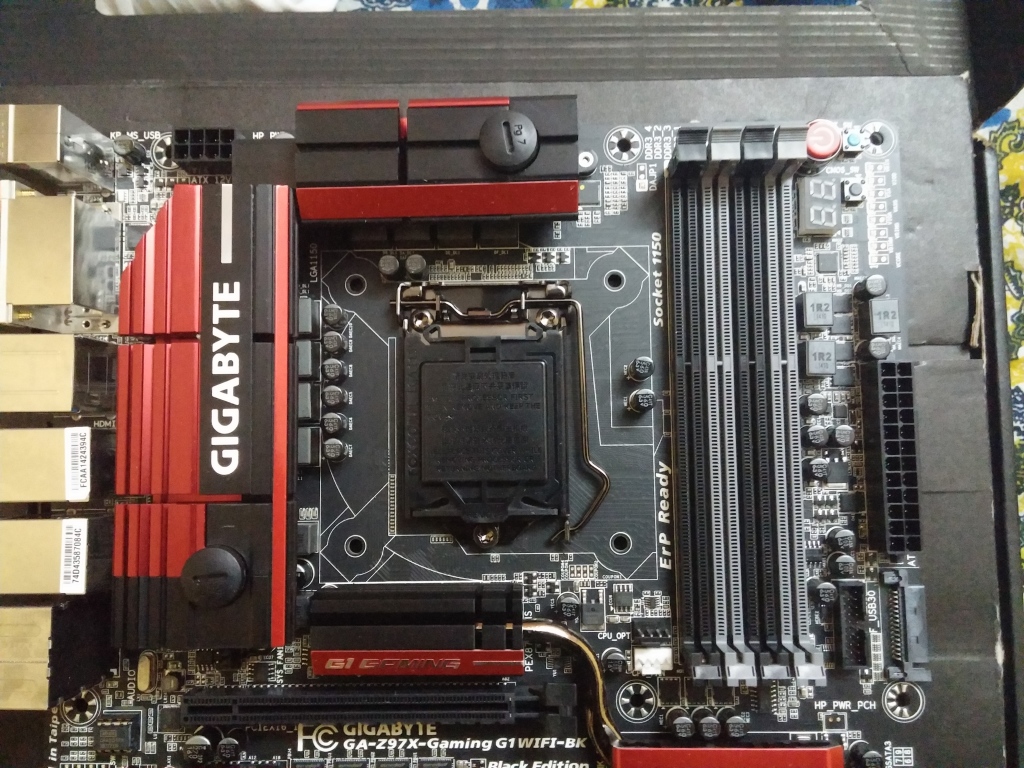
The CPU section is clean and offers enough space to install almost every CPU cooler. GIGABYTE continues to use 15 micron gold plating in the LGA1150 CPU socket. The single 8 pin ATX 12v connector is on top left hand corner of the motherboard. The top side of the G1BK looks surprising since there are no fan headers in this area. The right hand corner has two-digit debug LEDs, Power/RESET/Clear CMOS switches and voltage check points. The DRAM slots are nicely color coded for single channel/dual channel operation.
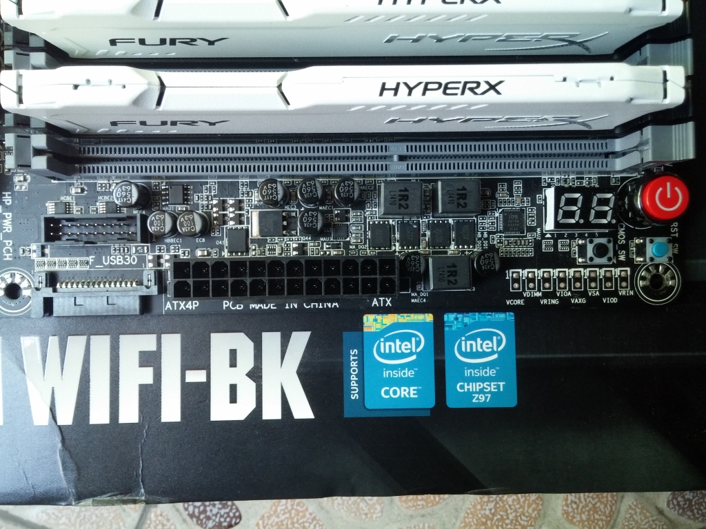
Moving downwards, the 24 pin motherboard power connector is in its usual place followed by USB 3.0 internal header and a SATA power connector (to provide additional power to the system for multi-GPU scenarios).

Then we come to storage connectors. For the G1BK, GIGABYTE skips the characteristic M.2 based storage options. Instead we get a single SATA-express connector and six SATA 6 GB/s connectors from the Z97 chipset, and four additional SATA 6 GB/s connectors from the dual Marvell 88SE9172 chips.

The bottom section of the motherboard is filled with a plethora of connectors. We get the usual ones like the front panel headers, three USB 2.0 internal headers and headers for Audio along with two BIOS switches (dualBIOS feature). There are a couple of fan headers here as well, so let’s look at the entirety of the motherboard for these now.
The G1BK has a total of seven fan headers. Of them, CPU_FAN and CPU_OPT are placed at an awkward spot between the first DRAM slot and the first PCIe x16 slot. But the SYS_FAN1 header, placed in a tiny space between PCIe x16 slot 1 and VRM heatsink poses the biggest trouble. With any sort of GPU installed in the first PCIe slot, connecting a fan in that header is a tedious chore. I am not sure why the top section of the motherboard was left out. Attaching a 240mm CLC where you need 3 connections (one for pump, two for fans, assuming you are using it in a push or pull setup) will require some creative cable management to say the least. The four remaining fan headers (SYS_FAN2/3/4/5) are on the bottom section of the motherboard.
Unlike most other boards which uses Realtek’s ALC1150 codec as the platform and then build upon it with additional features, GIGABYTE has chosen Creative’s quad core audio processor chip, Sound Core3D, for the G1BK. For filtering, Nichicon bipolarized audio capacitors are used, and a TI Burr Brown OPA2134 OP-AMP is there for amplification purposes. GIGABYTE also throws in two gain boost switches to choose between a standard 2.5x mode or a higher 6x mode gain amplification. As with GIGABYTE’s AMP-UP! Platform, the OP-AMP can be changed according to user needs (additional OP-AMPs sold separately). There is full path separation with red LEDs for the audio section, with different PCB layers being used for right-channel and left-channel audio, preventing crosstalk.
Located in the middle of the audio section and the second PCIe x16 slot is the Qualcomm® Atheros Killer E2201 chip which provides networking functions for one of the two available RJ-45 LAN ports.
Before jumping to the rear I/O, let’s look at the PCIe options provided with the G1BK. Since this is a top end board, GIGABYTE equips it with a PLX chip (PEX 8747) to enable Quad-GPU setups. We get four PCIe 3.0 x16 slots (operating at x8/x8/x8/x8 for quad GPU configuration), and three PCIe 2.0 x1 slots for expansion cards. Point to be noted here is that in case one uses a quad GPU setup, the fourth GPU will hang quite a bit off the motherboard, so sufficient preparations should be made before one venture into those domains. Between PCIe x16 slots 3 and 4 we see the two BIOS chips, termed M_BIOS and B_BIOS.

For I/O, there are a total of six USB 3.0 ports and two USB 2.0 ports. The USB 2.0 ports are gold plated, and GIGABYTE is advertising that these ports are capable of providing clean, low noise power to USB powered DACs. We have a solo PS/2 port beneath those USB 2.0 ports which can be used for either a keyboard or a mouse. For display outputs, there’s a DVI-I, a HDMI (supports up to version 1.4a) and a displayport (supports up to version 1.2) out, all gold plated for minimal noise. Dual LAN ports (one courtesy an Intel I217-V controller, another by the Killer E2201 controller) are also present but teaming is not supported.
Then we have five audio connectors, also gold plated, with an optical S/PDIF out. Overall, I am happy with the board’s layout except the fan headers. The color scheme is a hit or miss for most people. I, for one, think that GIGABYTE’s earlier green/black theme represented something unique, and with the red/black they are stepping into waters already muddied by other manufacturers.
GA-Z97X GAMING-7:
Once you get past the naming that sounds awfully akin to another manufacturer’s similarly themed series of motherboards, the Z97X-GAMING 7 looks like appealing. Coming immediately from G1BK the board looks rather empty, but that does not mean it doesn’t have its own share of features. This, by name, looks like the top-end offering from the GAMING series of boards (barring the GAMING-G1/GT boards of course), and at around $180 it is treading the space between top-end boards and value offerings.

Image Courtesy : GIGABYTE
So what do you get with GAMING-7? First off, the overall aesthetics is very similar to G1BK, with matte black motherboard and black/red heatsinks. The VRM and Chipset heatsinks are smaller than the G1BK, and are not connected by heatpipes. Understandably so, since there are no premium grade VRM components or PLX chip under the hood. The audio duties are handled by Realtek ALC1150, and there are no changeable OP-AMPs here. Only the Killer LAN is retained, and while we get M.2 storage, the 3 PCIe slots can only operate at x16/x8/x4 – so only 2 card multi GPU setups are practical here. The SATA ports are down from ten to eight, and the legacy PCI slot raises its head from obscurity, as well as the COM port header. But let’s look at the motherboard in a little more detail, starting as always from the top left hand corner.

The top left hand corner starts with the 8 pin ATX 12v connectors, placed between the I/O and the top VRM heatsink. The VRM heatsinks are small and are not interconnected. Underneath we get the power delivery circuitry, courtesy of International Rectifier’s IR3563B, an eight phase single loop PWM controller. There are 8 true phases at work here, same as the G1BK, but like the controller, the driver chip is a cheaper IR3598, driving the SiRa12DP High-side/Low-side MOSFETs (25A/6.5W). For DRAM, the GAMING-7 has two power delivery phases driven by an IR3570A controller. Point to note here that GIGABYTE is using 15 micron gold plating for the CPU socket, same as G1BK.
Between the top heatsink and the DRAM slots we have two fan headers, CPU_FAN and CPU_OPT. I cannot press this enough: this is the perfect spot for these fan headers. The color coded DRAM slots are next, and we get a full slew of four slots supporting up to 32 GB of memory and up to 3200MHz. On the right hand side of the DRAM slots are POWER/RESET/Clear CMOS buttons as well as the dual BIOS switches. The voltage checkpoints are also present in case anyone needs to measure them during extreme OC sessions.

Further down, we see the 24 pin ATX power connector in its default location, followed by the internal USB 3.0 header and the two-digit LED debug display right next to it. This is an odd location since the USB 3.0 internal connector is sure to obstruct the view to the display to some extent.
For storage, we get a single M.2 PCIe connector, a single SATA Express connector and six SATA 6 GB/s connectors from the Z97 chipset, while the single Marvel 88SE9172 chip adds another two SATA 6 GB/s connectors. The M.2 slot supports devices up to standard 2280 and is of M key type, so it uses a PCIe x4 interface and can theoretically provide up to 20 GBit/s of performance. But due to bandwidth limitations of the platform, only one amongst M.2 or SATA express or SATA slots 4/5 can be used at a time. Using one disables the other.
We also get a SATA power connector like the G1BK to provide additional power to the board to add stability in multi-GPU setups.

The bottom section of the board has the front panel connectors, two USB 2.0 internal headers, TPM and COM headers, and three fan headers (SYS_FAN2/3/4), with SYS_FAN4 being a 3-pin header. The two BIOS chips are located between the chipset heatsink and the USB 2.0 connectors/front panel headers, followed by the ITE I/O controller chips.
There are three PCIe 3.0 x16 slots, but again since there are no additional lanes via a PLX chip, these will operate at x16 for single GPU, x8/x8 for dual GPU, and an even more crippled x8/x4/x4 for triple card setups, so while AMD CrossFire is supported for tri-GPU, NVidia SLI is limited to only 2 cards. Practically speaking, GAMING-7 is more suited for dual GPU setups. We also get three PCIe 2.0 x1 slots, and a PCI slot, though the latter is sure to get hidden by the second GPU if installed, as will the second PCIe x1 slot if the GPU is installed in the first PCIe x16 slot.

The audio duties are handled by Realtek ALC1150, and there is separate shielded path at use for the audio circuitry in the PCB. The separation is lit up by LEDs which adds a nice aesthetic touch. For the audio, however, we see no additional frills. While there is an amplifier built in that can drive headphones up to 600Ω impedance, it is not user-replaceable. GIGABYTE, however, uses premium-grade Nichicon audio capacitors in the audio circuitry, and separate PCB layers for Left/Right audio channels. The advertised Front differential output is 115dB Signal-to-Noise ratio (SNR) playback (DAC) quality and 104dB SNR recording (ADC) quality.
Another fan header, SYS_FAN1 is between the first PCIe x1 slot and the VRM heatsink.
The Qualcomm Aetheros Killer E2201 chip can be seen located at straight lines to the space between the first PCIe x16 slot and the second PCIe x1 slot. This chip drives the motherboard’s sole LAN connector.

The I/O is standard-fare. GIGABYTE provides two PS/2 connectors here, one for mouse and one for keyboard, which is a nice touch. There are 4 USB 3.0 ports as well as 4 USB 2.0 ports, and a single LAN port covers network connectivity. The gold plated audio jacks and video outputs make their appearance here as well, and for the latter we get one each of a DVI-D, HDMI and D-sub ports, and there’s an optical S/PDIF out connector as well in the audio outputs.
UEFI run-down, bundled software
Since GIGABYTE’s BIOS/UEFI and bundled software package is pretty same across the board, I decided not to cover each board’s BIOS/UEFI/software packages separately and instead focus on the common things and the additional ones provided with G1BK.
GIGABYTE’s methodology has been a little different from other manufacturers when it comes to UEFI design. While they have moved to a more graphic-intensive approach in their recent motherboards, they have also retained the classic blue/black/white themed UEFI for easy access as well. The graphic-intensive section of the UEFI is dedicated to overclocking options predominantly, and with every motherboard carries a different theme based on which series it belongs to (GAMING series usually gets Orange/Red and Black, the Black Edition boards get a black and white). While this is commending for GIGABYTE to separate the OC section of the UEFI, the presence of the classic UEFI and same options in it can be quite confusing. I get the idea that GIGABYTE is sort of testing the waters here before they take the plunge for a full revamp of their BIOS/UEFI menu.
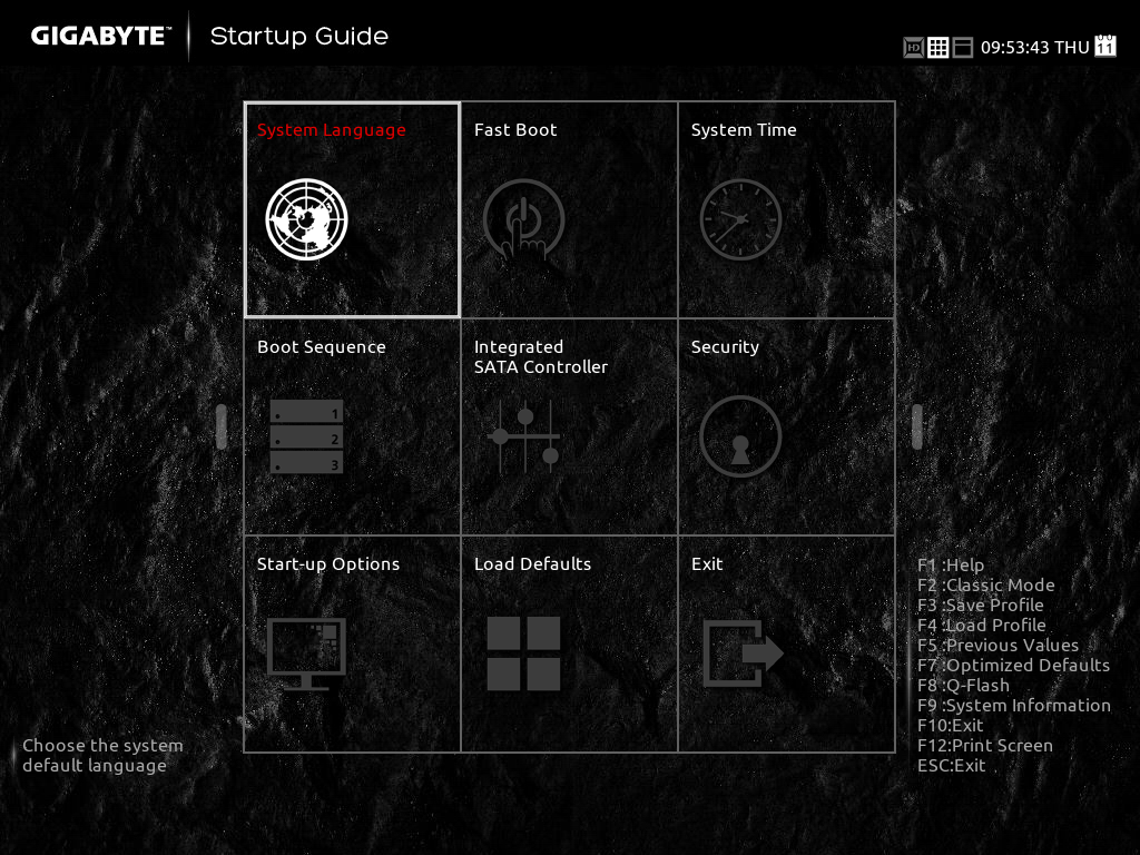
The first screen in the UEFI is a simple startup guide with options like Fast Boot, System Time, Boot Sequence, Load Defaults which can be changed on the fly here. There are also shortcuts to load and save profiles and show system info. Once F2 is pressed, the classic UEFI is launched.
The UEFI has the following sections.

M.I.T.: The Motherboard Intelligent Tweaker, or M.I.T. section has all the settings related to CPU/DRAM tweaking, with separate subsections for frequency/voltage settings.

The current status shows everything from CPUID, BCLK, Turbo Ratio/frequency, and Core Temperature for the CPU to detailed memory timings.

The Advanced Frequency Settings has options to set the CPU/DRAM frequencies either manually or by system defined values. There’s also option to set the iGPU clock from here.

Advanced CPU Core Settings is filled with CPU clock frequency tweaking options. One can also enable/disable CPU features from here.

As with most boards we’re seeing, there are pre-saved custom memory OC profiles which can be enabled from the Advanced Memory Settings.
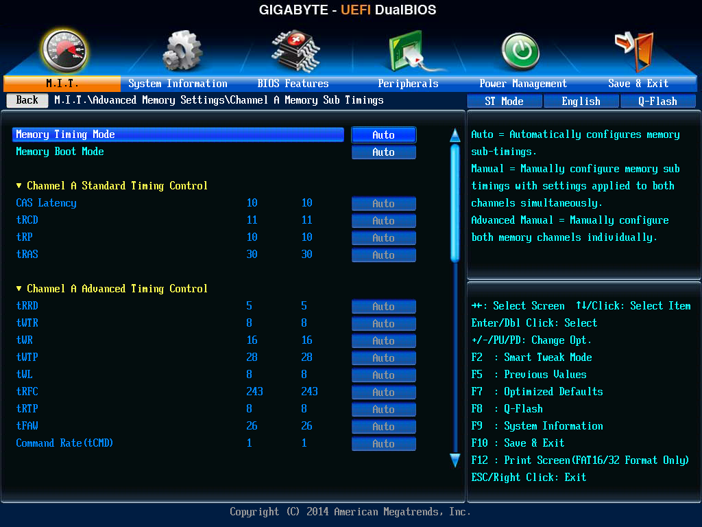
The more hardcore enthusiasts can tweak channel A/B memory subtimings manually as well.

As for Advanced Voltage Settings, we get submenus to control/tweak Power settings and CPU/DRAM/Chipset voltages.

PC Health Status shows temperature and frequency readings for core components.

System Information: A section with BIOS Version/Date/ID, System Language/Date/Time, and Motherboard model name.

BIOS Features: Basic/Advanced boot options.

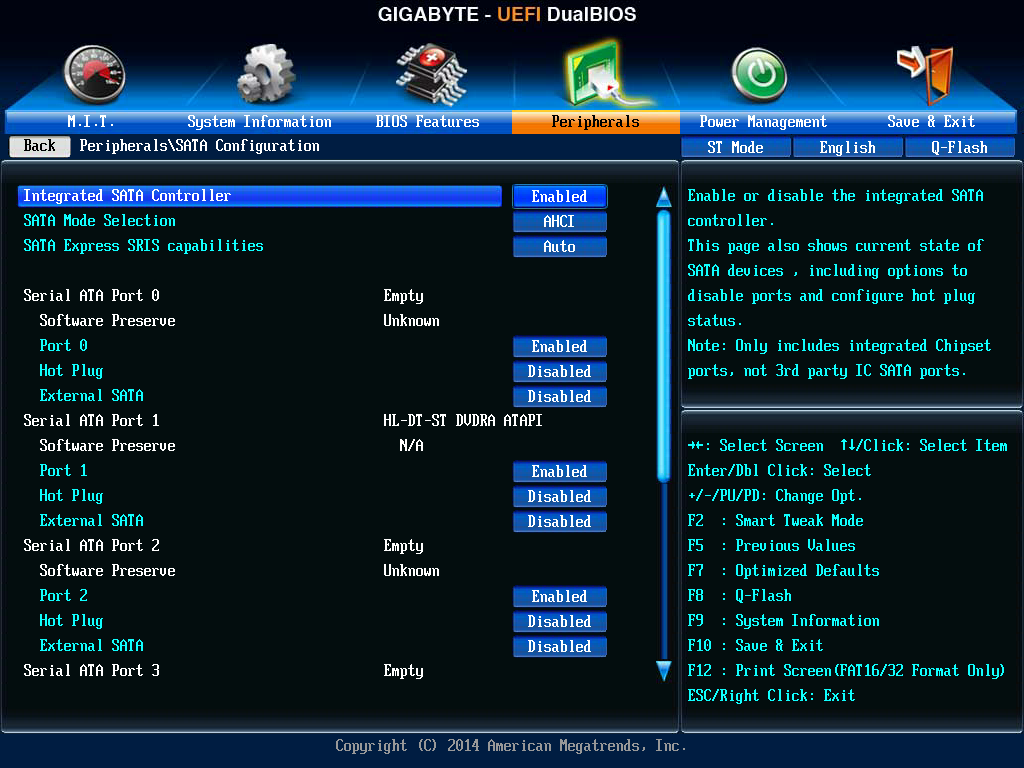
Peripherals: Has options for onboard controllers (USB/Audio/LAN), SATA configuration options.
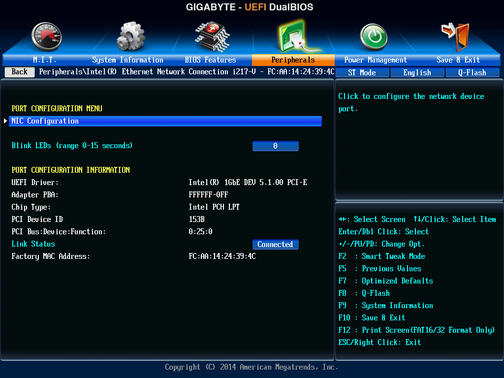
For G1BK you also get additional options for Intel i217-V like Port Configuration/NIC Configuration.
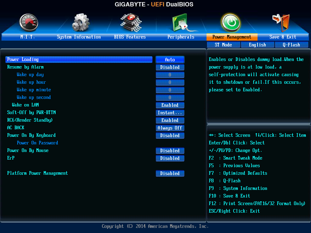
Power Management: Shut down/Start up power options, Power Management options.

Save & Exit: The name is self-explanatory. This section also contains the option for boot override.
The OC UEFI
The main section is surrounded by the current voltage/temperature readings for the CPU installed, DRAM frequency/voltage/individual channel timings, system voltage status, fan speed as well as a real time graphical representation of Voltage/Fan Speed/Temperature, so there’s a lot going on. I personally would have loved if these settings could have been hidden and the center menu could have been focused. While aesthetic wise this may look like a nerd-approved thing, for practicality and usage this is distracting.

The subsections at work here are:
Frequency: Contains CPU overclocking options.

Memory: Contains DRAM overclocking options with XMP settings and Channel A/B Memory subtimings.
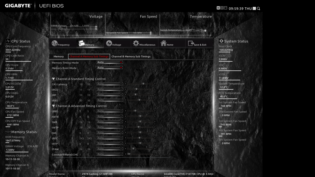
Voltage: Same as Advanced Voltage Settings in the Classic UEFI.

Miscellaneous: Same as Miscellaneous in Classic UEFI.
Home: A summary of current settings, and also contains the option to save/load profiles, and change boot sequences.

The Z97X-GAMING 7 has almost identical options here as well, albeit with an orange/black theme.

Z97X-Gaming 7 BIOS Screenshot courtesy : pcgameware.co.uk
Bundled Software:
I would like to go through this with a similar approach, i.e. chalk out the common things and then look at some additional features that come with G1BK. With every generation of processors and chipsets, I am amazed at how much functionality motherboard manufacturers are consciously trying to put into their bundled apps, and while we still get the common mixture of useful utilities and bloatware, the majority of things which come in the driver CD/DVD are in fact viable alternatives to popular software choices available via the Internet.
With that said, the collection of GIGABYTE branded applications are neatly packaged under a single section called ‘APP Center’ which pops up as a side menu with individual sections arranged in a columnar way. The default color scheme is red/black, but there’s option to change the foreground color to any of GIGABYTE’s color schemes (Orange/Blue/Green). The UI does not scale with resolution, that’s something GIGABYTE need to fix. On my 1440p screen, they were still big spaces with little to no words, and the entire thing, while aesthetically being pleasant and minimalistic, can do with a little scaling.
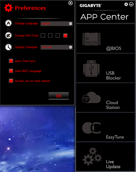
The different sections we’re looking at here are:

@BIOS is the BIOS information and update utility. For updating the BIOS, there are options to do it from a locally saved file or downloading it from GIGABYTE’s server. You can also save the current BIOS in a file as backup.
EasyTune has been GIGABYTE’s de facto overclocking software/application for as long as I can remember, and with the introduction of the APP Center it has found a place inside the app ecosystem. The different tabs we used to get with older iterations of EasyTune are now on the left hand side, and allow the user various tweaking functionalities.

Firstly, the Smart Quick-Boost can jack up the CPU speed to pre-configured profiles (Light/Medium/Extreme/Energy Saving/Default/Auto Tuning), with speeds ranging from 4.0 GHz to a steep 4.6 GHz. I am not a fan of auto overclocking and more often than not the voltages applied to the CPU with these overclocks can be toned down, but the option is there for people who do not want to tinker much and want to achieve a boost in performance/speed.

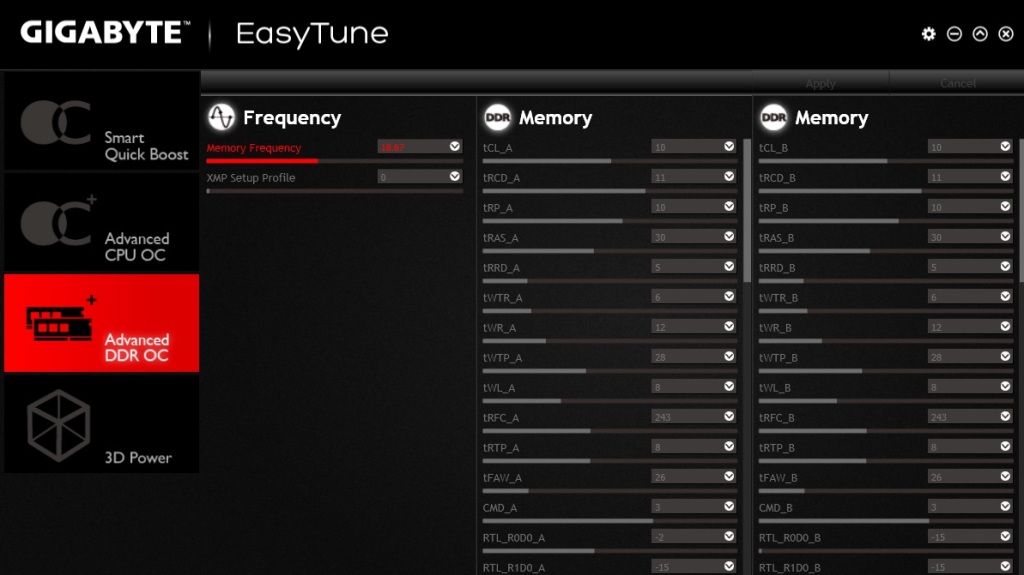
The ‘Advanced CPU OC’ and ‘Advanced DDR OC’ sections have OC options for CPU and DRAM respectively with a fair bit of settings available to mess around with. One point I want to make here that the CPU settings get applied instantaneously, while the RAM tweaks, especially toying with frequency requires a reboot to take effect.

The 3D Power menu can be used to alter PWM power phase, voltage and frequency. Lastly, EasyTune also opens a monitoring menu where all the current frequency/voltage/temperature readings for components are displayed.

EZ Setup is basically a GIGABYTE wrapper on top of Intel’s technologies like Smart Response, Rapid Start & Smart Connect. Also in the mix are modes to switch the disk mode to AHCI/RAID, and XHD (eXtreme Hard Disk) to add another HDD in an existing RAID array, specifically RAID 0.
Fast Boot is an interface on Windows to allow fast boot and boot options post an AC power loss.

Game Controller allows a user to define keyboard hotkeys and change mouse sensitivity.
ON/OFF Charge allows quick charging of an iOS device through USB power even when the PC is turned off. GIGABYTE claims the quick charging is actually up to 40% faster.
Smart TimeLock can control when the PC is to be turned on and/or off.
Smart Recovery 2 is a backup utility. This can be used to back up a partition or an entire HDD for as frequent as an hour.

System Information Viewer is self-explanatory. This also contains GIGABYTE’s fan control utility.
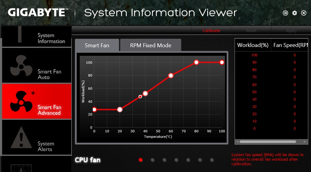
For fan control also, GIGABYTE provides Auto/Advanced modes, with the former having presets (Full Speed/ Standard/ Performance/ Quiet) and the latter more fine tuning options.
USB Blocker can block certain types of USB devices which will then be ignored by the OS once plugged in.
Update Center searches the internet and gives you a list of available updates which can then be either downloaded simultaneously or one by one.

Cloud Station:
Cloud Station is something I saw first in G1BK. This is GIGABYTE’s amalgamation of several networking/remote monitoring utilities into one.

HomeCloud allows you to share your files between your computer and your iOS/Android smartphone or tablet via cellular network/WiFi. This is done through GIGABYTE’s Cloud Station app.

Remote, as the name suggests, allows the user to control the mouse/keyboard/Windows Media Player from his smartphone/tablet.
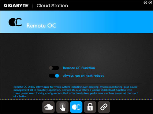
(Remote OC Image Courtesy : GIGABYTE)
Remote OC allows you to tweak and overclock the system remotely through a smartphone/tablet and even allows you to shutdown/reboot it. It also provides a system monitoring function.
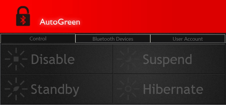
Auto Green enables to change/monitor the system’s current power state via a smartphone/tablet through Bluetooth. When the device is out of range, the system enters the predefined power saving state and gets auto-locked.

Lastly, HotSpot can be used to create a virtual wireless access point to share the available network connection bandwidth.
Box Contents
Z97X-GAMING-G1 WIFI-BK Box contains
- Six braided black SATA cables.
- One rigid tri SLI and one rigid quad SLI connectors, one each of flexible SLI/CrossFireX connectors.
- A front panel box with two USB 3.0 ports. This can fit in a 5.25” bay.
- PCIe based WiFi module and a USB 2.0 cable which fits into this module, possibly to enable monitoring.
- WiFi antenna
- Driver CD, Rear I/O Shield, Manual, Multilingual Installation guide, GIGABYTE Ultra Durable and Black Edition Stickers
Z97X-GAMING 7 Box contains
- Four black SATA cables
- One flexible SLI connector
- Driver CD, Rear I/O Shield, Manual, Multilingual Installation guide, GIGABYTE Ultra Durable and GAMING G1 Stickers
Test Setup, Overclocking, General Performance Comparison:
I tested these two boards in a similar setup.
- Intel Core i7-4770K, Haswell, 4C/8T, running at stock 3.5GHz. Turbo 3.9GHz
- GIGABYTE Z97X-GAMING-G1 WIFI-BK / Z97X-GAMING 7
- Kingston HyperX Fury 8 GB Dual Channel DDR3-1866, 10-11-10-30 CR1
- Western Digital Caviar Blue 250GB HDD
- Corsair HX750W 80Plus Silver Power Supply
- Corsair Carbide Air 540
- CPU Cooler SVGTech HOC 40 w/ Gentle Typhoon AP-15 fans
- HIS AMD Radeon HD6870 GPU, Barts, 900/1050MHz
- Dell Ultrasharp U2713HM monitor, 2560×1440@60Hz
I wanted to see how much these two boards were similar in performance, and if the premium components used in the G1BK had any effect on benchmarks. Without further ado, let’s dive in.
First up, the AIDA64 Benchmark suite. FinalWire’s AIDA64 is a popular system monitoring tool and comes with its own set of benchmarks for stressing the CPU and Memory. Here’s what their benchmark tests contain.
Memory Tests
Memory bandwidth benchmarks (Memory Read, Memory Write, Memory Copy) measure the maximum achiveable memory data transfer bandwidth. The code behind these benchmark methods are written in Assembly and they are extremely optimized for every popular AMD, Intel and VIA processor core variants by utilizing the appropriate x86/x64, x87, MMX, MMX+, 3DNow!, SSE, SSE2, SSE4.1, AVX, and AVX2 instruction set extension.
The Memory Latency benchmark measures the typical delay when the CPU reads data from system memory. Memory latency time means the penalty measured from the issuing of the read command until the data arrives to the integer registers of the CPU.
CPU Queen Benchmark
This simple integer benchmark focuses on the branch prediction capabilities and the misprediction penalties of the CPU. It finds the solutions for the classic “Queens problem” on a 10 by 10 sized chessboard. At the same clock speed theoretically the processor with the shorter pipeline and smaller misprediction penalties will attain higher benchmark scores. For example — with HyperThreading disabled — the Intel Northwood core processors get higher scores than the Intel Prescott core based ones due to the 20-step vs 31-step long pipeline. CPU Queen test uses integer MMX, SSE2 and SSSE3 optimizations.
CPU PhotoWorxx Benchmark
This benchmark performs different common tasks used during digital photo processing.
It performs the following tasks on a very large RGB image:
Fill the image with random colored pixels
Rotate 90 degrees CCW
Rotate 180 degrees
Difference
Color space conversion (used e.g. during JPEG conversion)
This benchmark stresses the SIMD integer arithmetic execution units of the CPU and also the memory subsystem. CPU PhotoWorxx test uses the appropriate x87, MMX, MMX+, 3DNow!, 3DNow!+, SSE, SSE2, SSSE3, SSE4.1, SSE4A, AVX, AVX2, and XOP instruction set extension and it is NUMA, HyperThreading, multi-processor (SMP) and multi-core (CMP) aware.
CPU ZLib Benchmark
This integer benchmark measures combined CPU and memory subsystem performance through the public ZLib compression library. CPU ZLib test uses only the basic x86 instructions, and it is HyperThreading, multi-processor (SMP) and multi-core (CMP) aware.
CPU AES Benchmark
This benchmark measures CPU performance using AES (Advanced Encryption Standard) data encryption. In cryptography AES is a symmetric-key encryption standard. AES is used in several compression tools today, like 7z, RAR, WinZip, and also in disk encryption solutions like BitLocker, FileVault (Mac OS X), TrueCrypt.
CPU AES test uses the appropriate x86, MMX and SSE4.1 instructions, and it’s hardware accelerated on VIA PadLock Security Engine capable VIA C3, VIA C7, VIA Nano and VIA QuadCore processors; and on Intel AES-NI instruction set extension capable processors. The test is HyperThreading, multi-processor (SMP) and multi-core (CMP) aware.
CPU Hash Benchmark
This benchmark measures CPU performance using the SHA1 hashing algorithm defined in the Federal Information Processing Standards Publication 180-4. The code behind this benchmark method is written in Assembly, and it is optimized for every popular AMD, Intel and VIA processor core variants by utilizing the appropriate MMX, MMX+/SSE, SSE2, SSSE3, AVX, AVX2, XOP, BMI, and BMI2 instruction set extension. CPU Hash benchmark is hardware accelerated on VIA PadLock Security Engine capable VIA C7, VIA Nano and VIA QuadCore processors.
FPU VP8 Benchmark
This benchmark measures video compression performance using the Google VP8 (WebM) video codec Version 1.1.0 (http://www.webmproject.org). FPU VP8 test encodes 1280×720 pixel (“HD ready”) resolution video frames in 1-pass mode at 8192 kbps bitrate with best quality settings. The content of the frames are generated by the FPU Julia fractal module. The code behind this benchmark method utilizes the appropriate MMX, SSE2, SSSE3 or SSE4.1 instruction set extension, and it is HyperThreading, multi-processor (SMP) and multi-core (CMP) aware.
FPU Julia Benchmark
This benchmark measures the single precision (also known as 32-bit) floating-point performance through the computation of several frames of the popular “Julia” fractal. The code behind this benchmark method is written in Assembly, and it is extremely optimized for every popular AMD, Intel and VIA processor core variants by utilizing the appropriate x87, 3DNow!, 3DNow!+, SSE, AVX, AVX2, FMA, and FMA4 instruction set extension. FPU Julia test is HyperThreading, multi-processor (SMP) and multi-core (CMP) aware.
FPU Mandel Benchmark
This benchmark measures the double precision (also known as 64-bit) floating-point performance through the computation of several frames of the popular “Mandelbrot” fractal. The code behind this benchmark method is written in Assembly, and it is extremely optimized for every popular AMD, Intel and VIA processor core variants by utilizing the appropriate x87, SSE2, AVX, AVX2, FMA, and FMA4 instruction set extension. FPU Mandel test is HyperThreading, multi-processor (SMP) and multi-core (CMP) aware.
FPU SinJulia Benchmark
This benchmark measures the extended precision (also known as 80-bit) floating-point performance through the computation of a single frame of a modified “Julia” fractal. The code behind this benchmark method is written in Assembly, and it is extremely optimized for every popular AMD, Intel and VIA processor core variants by utilizing trigonometric and exponential x87 instructions. FPU SinJulia is HyperThreading, multi-processor (SMP) and multi-core (CMP) aware.
Results:
I also ran a couple of CPU intensive benchmarks.
TechARP’s x264 HD 5.0 benchmark measures how fast a CPU is able to encode a full HD video clip into a x264 video file.
3D Particle Movement is a new benchmark penned by AnandTech’s venerable Ian Cutress. Here’s what he says about it : “Simply put, it is based on 3D Random Movement algorithms. There are a fair few when looking at the literature, and all use a variety of different mathematical formula to achieve the same result. Some are more trigonmetric heavy, some use random numbers generated using normal or variable distribution algorithms. When moving a single item a few spots, the speed of each algorithm is of no concern, but when you move into scientific computing and have to deal with billions, having the best algorithm for the job is on the table.”
POV-Ray, or Persistence Of Vision Ray Tracer, has a benchmark of its own to test CPU performance.
Cinebench is a popular rendering benchmark and can test single core as well as multi-core performance of a CPU.
WPrime is a leading multithreaded benchmark for x86 processors that tests your processor performance by calculating square roots with a recursive call of Newton’s method for estimating functions, with f(x)=x2-k, where k is the number we’re sqrting, until Sgn(f(x)/f'(x)) does not equal that of the previous iteration, starting with an estimation of k/2. It then uses an iterative calling of the estimation method a set amount of times to increase the accuracy of the results. It then confirms that n(k)2=k to ensure the calculation was correct. It repeats this for all numbers from 1 to the requested maximum.
Results:

I also ran a compression/uncompression benchmark from 7 Zip, a freeware utility. I excluded the result from the previous list only because the results were in the 20000+ numeric mark and would have gone out of range for other benchmark results.

The results are not surprising. While the G1BK just nudges past the GAMING 7 in most benchmarks, the difference is not substantial. The highest difference between the two boards is in CPU AES bench, and that too a measly 6%, and in one test the Gaming 7 actually manages to beat the G1BK.
Overclocking experience:
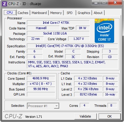
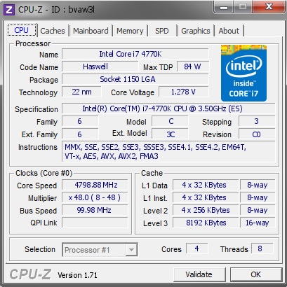
With both boards I had a pleasant time overclocking. While the auto overclock to 4.7 GHz on both boards through EasyTune shot the VCore to a steep 1.4 volts, I was able to shed some of that voltage and still retain the OC. The Black Edition motherboard even allowed me to manually overclock the 4770K to 5 GHz, but it wasn’t stable even with increased voltage. I did not push beyond 1.35 volts as VCore for both boards. The maximum stable overclock for both boards was 4.7 GHz, though the Gaming 7 for a brief moment allowed me to push to 4.8 GHz the same voltage ( I was lucky enough to submit a CPU-Z validation before the system crashed).
4770K on the Z97X-GAMING-G1 WIFI BK
Maximum OC on the Z97X-GAMING 7
For memory, I was able to push the DDR3-1866 sticks to DDR3-2666 (13-16-15-36) using the G1BK, while the Gaming 7 topped out at DDR3-2400 (13-15-13-36).
Conclusion:

I thoroughly loved testing both the GAMING-G1 WIFI BK and the GAMING 7. They both come with their pros and cons and then GIGABYTE has some quirks of its own, but overall I like them both. Let’s look at them individually.
The Z97X-GAMING 7, at Rs.16,900, is a good motherboard, offering a mixture of good performance and expandability. It should run dual-GPU setups with ease (something that I didn’t get the chance to test, sadly) and then some, has M.2 based storage as well as SATA-Express, upgraded and EMI-shielded audio, Killer E2201 LAN – pretty much enough bells and whistles for a good gaming PC. Where it falls short is that GIGABYTE applies a less aggressive MultiCore Turbo for the CPU by default, so the scores are ever so slightly less than their top-draw, the WIFI-BK. Secondly, though the Killer chip is potent, an Intel based LAN is far more stable and reliable option. Third, though the audio section is great, I would have loved to see upgradable OP-AMPs make their way into this board as well. Aesthetics could have been better, but then I am really nitpicking. It overclocks like a champ, has close to flagship level stock performance, and offers well enough overall value.
The Z97X-GAMING-G1 WIFI BK is a different beast at close to Rs.30,000. It is clear that GIGABYTE went all out here : Quad-GPU support through a PLX PEX8747 chip, Creative Sound Core3D Audio with Ti Burr Brown OP-AMP (upgradable), premium grade VRM/PWM components from IR, Dual Intel+ Killer LAN, gold plated USB 2.0 ports, ten SATA ports, seven fan headers, WIFI ac module – the list is endless. But in the end, while the board barely manages to beat the GAMING 7 which retails for almost half its price, it achieves higher overclocks for both CPU and memory. This board caters to a niche section, and unless you are building a 2+ GPU system, it is hard to justify shelling out this much amount of money just for the added features like Audio, Intel LAN, and onboard WIFI/BT.


